From this original thread on Honda-Tech.com.
http://www.honda-tech.com/zerothread?id=1165546
Since this was 3rd Gen specific, felt transferring the info over to our site were it is easily accessed would be much more useful and beneficial to the best 3rd Gen community on the net!!")
I take no credit for this info, just reposting it were it will most useful.
This will benefit the DIY's and those needing those most pertinent information on this swap.
Sean
-------------------------------------------
Section I.
A LOT OF THINKS ARE CHANGED AND IMPROVED DURING THIS PROJECT.
REAd ALL PAGES OR ASK FOR HELP OVER THE POSTS!
This page will be edited for final write up!
So, where do I begin!

1) The car and electronics's.
If you have 90-91 lude it will be less job with electrical installation. Other wise from mechanical point of view no differences between 88-89 gen Preludes.
The 90-91 pgmfi ludes have OBD-1 type ECU international system. That means, you can use any OBD-1 Honda wiring diagram, all functions of sensors will be similar and addresses of pins in ECU will be the SAME !!!
For example:
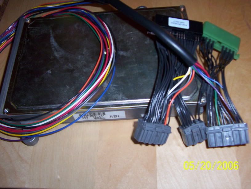
You can connect to your 1990-91 Prelude 1994 year P13 ECU without any connector swaps or mods.
Must be like that: (*Note: The OBD1 plugs are the three grey plugs. this is what is in the 90-91 ludes.)
1.) If you have 88-89 Prelude with older OBD0 system and carburetor.
In pgmfi case get the OBD-0 to OBD-1 wiring harness swap(the picture above is the Jumper harness for the 88-89 OBD0 ludes) connectors or any HONDA OBD1 92-95 ECU connectors from junk yard. Just do a solder job switching connectors using the wiring diagram.
In carburetor lude you must change all the car's fuel and electric wiring system with fuel tank and fuel pump in it. That's not difficult job if you have Honda manual.
2.) Engine wiring.
During the swap I found out that the most difficult stuff was with the coil and igniter unit proper connections. That's why I will place more attention on those areas.
I do not have any experience with US market H22 engines and as I understand there are popular outside coil ignition systems.
Till now, I have only dealt with the JDM H22A engines with inner coils.
All 3rd gen Euro ludes come with outside coil ignition systems. That's why there must be some changes in engine wiring during JDM H22 swap.
Here are H22A OBD-1 92-95 wiring diagram:
http://www.we-todd-did-racing....D.jpg
http://www.we-todd-did-racing....D.jpg
Here is B20 OBD-1 90-91 year wiring diagram:
http://www.we-todd-did-racing....D.jpg
The Diagrams are very similar. But in reality the positions of the sensors on engine and car have different locations. Between 3rd and 4th gen ludes.
The sensors and connectors are different. Fortunatley 95% of them are wired in similar way.
3.) How to connect engine with ECU.
I have on H22A engines the JDM type wiring, which is wired to left side for right hand car. The main connectors are OBD1 type. Those main connectors are connected with under dashboard wiring and goes to ECU, relay box, fuel relay and different other ways.
That's why the best way is to go with the original car and engine wiring harness system. And adapt it for the new engine. " Do Not use the new engine wiring harness and try to adapt the car wiring and connectors for it. "
That means, in this swap I will be using the B20A engine wiring harness as base for the H22A engine. I will Install from the H22A engine the original wiring. Don't throw it away. It will be like donor for new hybrid wiring.
3.) The differences!
Above JDM H22A wiring
Below B20A wiring

Numbers mean:
1. The main connector junction. All wires from the sensors go to the ECU on JDM H22A car.
2. The main connector junction. Almost all wires from the sensors go to the ECU on 3rd gen prelude car.
3. To the relay box (+) power cable from alternator
This is a closer view of the number 2 and 4 connectors of the B20A wiring.

4. To the relay box (+) power cable from alternator
5. The injector connector assembly with the idle valve connector.
Here I will put a picture of the injector connectors, they are the same as the idle valve connector. And the B20A connectors will fit perfectly on the H22A injectors:

6. The injector connector assembly with the idle valve connector.
7. The Alternator (+) power cable and the control connector.
These are the same with alternator connectors:

8. The Alternator (+) power cable and control connector.
9. The Distributor connectors.
10. Distributor connectors
Here you can see how different the distributor connectors are. The Grey ones are the H22A connectors:

11. Oil pressure sensor connector. It's a plug type connector.
12. Oil pressure sensor connector. It's connected with the sensor using the bolt.
13. Knock sensor
14. Resistor box connector. It could stay in that position. If you use OBD1 type resistor box, then you must to change to OBD1 type connector.
In this pic you can see the main differences in the wiring.
MAP SENSOR
The H22A and B20A wiring don't have the MAP sensor connector. It's separately wired from the ECU to the MAP sensor.
I'm using the stock MAP from the 3rd gen. Just pull it out from the big black vaccum box where the other EGR solenoids are.
So, I will just use the vacum box MAP sensor(only). Make a space in the engine bay for it. There is all ready a good connection with the ECU and most important, it's correct with OBD1. It has the same pins to the ECU even with the different generation of ECU's.
Connect it with vacum line to intake manifold. No any error codes on the P13 ECU, it work's fine. No wiring mods needed.
a.) Both wire harnesses have the same connectors:
Speed sensor
Lambda (O2) sensor
Injector's
TP - Throttle position sensor
IAT - Intake air temperature
Idle valve sensor
Water temperature sensor to ECU
Water coolant fan sensor
Water temperature sensor to dash board
Starter signal sensor
Shift position sensor
Alternator sensor
b.) The Different connectors are:
EGR valve lift sensor
Distributor connectors
Oil pressure
Main connectors to ECU
c.) The B20A wiring harness does not have the connectors to:
VTEC oil pressure sensor
VTEC oil pressure switch sensor
Knock sensor
ECT sensor near thermostat on the H22A
Using the wiring diagram and this information I will make the hybrid wiring harness for the H22A engine, and the base wiring will be from the B20A engine. The skeleton must look like this after the modificaiton for H22A engine:

Put the wiring harness on the engine and check that all wires have the right length and that all connectors are connected properly in the right positions.
All cables must be soldered and isolated properly. Especially the distributor and Knock sensor cables.
Final wiring after all modifications must look like this:

The distributor connection!
Well, there are some important differences.
The connectors:
Change them when making the wiring harness. Change all the wires, and make them full length to the main connectors. And do a good solder job there. Near the big white main connectors. Do not change them near the distributor, Because there are much higher engine temperatures in the engine bay. And you will touch the distributor connectors many times before you finish the swap. That could damage the soldered connections.
The JDM H22A distributor is fitted with (3) important sensors, ignition coil and igniter unit. See wiring diagrams for:
CYL - Cylinder sensor
TDC - Piston up point sensor
CKP - Crankshaft position sensor
ICM - IGNITER UNIT
In this picture you can see the distributor connector. I'm holding the igniter unit cable Yellow/Green which must be connected to the ECU A21 pin:


So, you can see on the wiring diagram that the ignition unit built into the distributor on H22 engines. This is the only cable which is not on the 3rd gen ludes original B20 engine wiring harness. That's if we are talking about ignition.
Coil connection:
On the 3rd gen ludes the coil is mounted in engine bay near the main connectors, red circle indicates the old place of the outside coil:

It has (1) pink and (1) grey smalle connector. Both connectors have similair cables. Blue and Black/Yellow. Remove those connectors. So, we will be going to need only the bigger cables. And the small pare cables just isolate them, you don't need them anymore.
Here is the picture of how it must look like:

Then do a nice connector on the wiring for a safe connection:

I don't think that it will be a problem to get that kind of connector at the junkyard from any 4th gen lude or Accord.
OK, I guess this could be the final write up about the electronics and connections.
Tehnical write up soon. Fell free to ask any question!
Section II.
During the project our mine idea was to build it with less modified parts. Any way it's not possible to do that. Mounts must costume made ( H22 Mounts - Group Buy Part 4 Produced by www.azracemachine.com). And we did them. There must be done some small changes during final mount kit making. Because find out problems with power steering pump belt. That's why I can't post any picks, measures of mounts.
The H22 Engine is wider and longer that's why there are lot of differences in engine position in car body.
One of important question is what kind of axles to use.
AXLES (this link is the most uptodate info: Hybrid Axles: H22 with AZ Motor Mounts )
Well, there are did many tests and we get right one. Combination with OEM stock parts. There are possibility to order costume fabricated axle kit. For European Guy's this will be too expensive to order axle kit from US. And I don't see the reason why to order them, if it's possible go with stock parts.
*(Note This set up does not work

Explaining:
1 and 6 on pic:
They must be from a 3rd gen. The 4th gen lude and Accords outside joints have longer fingers, but the same diameter and groove number.
2 and 5.
The most important parts. Those two shafts must be from 92-95 Accord's or Rover 620. Only passenger side shaft will fit correctly on both sides on 3rd gen H22A swap.
Each beam could not be longer than 410 mm. Thats the measurement of shaft without the inner and outer joint.
3 and 4
Inner joints fit from
92-2000 Prelude F, H series.
92-2000 Accord F series.
92-2000 Civic B series.
92-2000 Integra B series.
When buying the inner joints in junk jard, check for movement. Not sid to side <> this way, but up and down (rotation way). It's important because with that movement inner joint will live a short life. Driving will be uncomfortable, there will be strange noises from suspension side. Or just buy the new parts.
Here are supportinf pictures. How to change outside joint.
Sustain the axle beam in vice. About 45 degrees, joint outside and down.

Update on axles:
4th gen and 3rd gen axles are to long. The outside axle shafts are too long. And and I can't put the wheel in place. They are about 10 mm too long. So, I used Civic VTI axle shafts they were shorter. I swapped the outside joints on the axles from a civic to the prelude 3rd gen. Then, I can put the wheels in place. But it's very tight. Any way axles seem like they might be a little bit too long ~2 mm for both sides. No space for movement in inner joints. When turning the steering wheel, the engine moves up and down a little bit too much. And wheels don't spin very well.
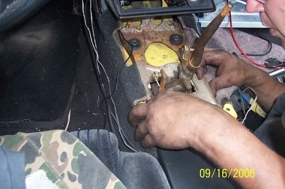
Shifter Info:
The 3rd gen lude shifter and shifter cables don't work with H or F series transmission.
Must to replace the shifter and shifting cables from:
Accord 92-97
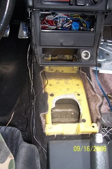
Prelude 92-96 You can easy install the shifter plate in same location where older was. Remove the small plate in body tunnel under original shifter plate. It holds from factory with silicone glue. Must to drill the 4 new holes, they are not bolt on.
When installing the shifter to the car, I would suggest removing the rubber bushings from the top and the bottom of the plate, and just mount the shifter metal-to-metal.
the shifter feels MUCH more solid this way, and the side effects are little-to-none.
Off course! We will going to use 4 mm steel for making the mounts.
Section III.
Can be use B20 trany with autotrany axles from Accord. And there must be cut some material out from engine block for axle join. The trany is little bit too small for H22A engine block.

Or must be costume made H22 block axle mount.

A lot job there. Pressing out bearing, new mount. There are needed professionals help from machine shop. And it's expensive, too long. Any way timing side mount must be costume made too. So, counted all those problems. We decide to go with 4 gen trany. Less problems(money), bigger clutch, stronger axles....
First of all I did by my self all measure and CAD job. There are two mount pares. One for timing belt side, other for trany. As I wrote, front and back mounts could stay stock with some mods. I did this way because I like to show that it's easy and much cheaper. Only (sadly) need to make new side mounts. That mean, we need 4 different details. They cost different money because thay are different design.
They will cost for me, for one car 250$....
originally posted by Daily Interlude » Can you give a full explanation of how you did the axles? What parts did you use from the 3rd gen and what parts from the 4th gen?
Change only outside joins on 4 gen axles. Change to 3 gen joins. This is how it must work. After 1-2 weeks I will give you answer how exactly will be.
Wiring:
1. Take of original B20 wiring from B20 engine.
2. What kind ECU system your car have, check that. OBD-1 all gray connectors. OBD-0 2 black, 1 white connector.
3. Put together H22 and B20 wiring, just look at them. You will find a lot same connectors, a lot different and missed for H22 engine.
4. If you have OBD-1 B20 ECU that mean all B20 sensors and connectors working by OBD-1 wiring diagram of Honda. The big connectors which separate wiring between motor and salon could stay. 5. Just wire in to original B20 wiring all necessary connectors from h22 wiring. Open both wiring's till cables. You will find alot of cables in different colors. So, it will not be difficult to follow by colors of cables and installing entire plugs with cables from H22 to B20 wiring. Get H22 wiring diagram, that will help a lot. Get that kind of diagram which not only show connector name and where it belong in ECU, but in same time with cable color. There are that kind of diagrams from Honda manuals.
You can use this info about harness mods. I just take out the old distributor cables and put back in wiring new H22 cables with connectors for H22 distributor. Watch in wiring diagram, which cables have the same function which missed. There will be lot of cables which you can't add and connect them with ecu using B20 big white connectors. There are the best way to find mother and father connector. Add cables from one side to other side. I mean from engine to ECU. That is not so good if you just directly install cable from engine to ECU without connector. Maybe after some time you are going to do some mods for engine and there will be necessary to swap it out. It will be much easy to disconnect wiring in connectors, not cut them.
B21 to H22 wiring is basically the same as doing the H23 to H22 swap. Just have like 4 or 5 wires to add and maybe change some connectors.
Both are OBD1
Some pics of wiring:
Stock B20 wiring connectors for inectors. They will work with H22 injectors. In the midle of pic there is idle run vale connector. It's B20 too

Resistor box connector, actulay it could stay OBD-0(white plug), but we decide to change it.

Distributor connectors

This is half Prelude B20 and H22 wiring.


Stock Header:
The header end on B20 are much longer as on H22. Must re longer exhaust pipe. B20 O2 sensor have the same 4 wire grey plug as on H22, so B20 O2 sensor can be used for H22 too.
About Shifter Cables:
About shift cables and shifter.
The all B20 shifting system can be used too for h22 trany. Only need to rebuild mount for shifter cables on H22 trany. Most of times it's from aluminum. So, need some good welder help. Only one cable is too short for about 50 mm (~ 2 inches). Not the cable as it self, but bracket neck with groove.
Distributor info:
If you have H22 without original distributor then you can use H23 also. Find by wirng which cables on B21 support "Crank position; Top dead; Cylinder sensor". There will be black/yellow for induction and blue cable. On lude 3 gen induction is out side from distributor.
Cut of old connectors and add those plugs which have you H23 or H22 distributor. I just saw on one 2000 lude which was received from US. On H22A4 there is out side induction. Not in distributor. We don't have in Europe like that. We have like on JDM's inner induction.
We uninstalled the outside coil. And use the OBD-1 inner coil and distributor. Less parts in engine room and less wiring.
Intake Manifold:
The IAB electrical wiring only goes to the black vacume box. From there, a vacume line goes to the actual piece that's on the driver's side of the intake manifold which controls the opening and closing of the butterflies.
Posted by: shantesonse013627.blogspot.com
Source: https://www.preludepower.com/threads/h22-swap-from-honda-tech-write-up.256587/


0 Komentar